
Following the previous article, I now concentrate on design choices and implementation.
The device was an OHRM gadget, so there was already some sensors available which could be used:
- A motion sensor, basically a combo accelerometer/gyroscope which can also say “there is some motion” or “there is no motion” (we discard the other functions implemented in the component for this purpose).
- A light sensor, which is also used for computing the OHRM. It measures the ambient light.
- Some information from the OHRM process itself (whether there is some Heart Rate detected or not)
And as usual, things are more complicated than in the textbooks 🙂
- Those sensors are not sampled at the same rate
- Some sensors have memory. For example, if “no motion” is detected once, then this info will not be fired again until “some motion” is detected
- Not all the sensors have the same type of outputs (analog outputs and logical outputs)
Thinking about a suitable algorithm for implementing this Sensor Fusion controller, I realized that the kind of questions to be answered was:
“If the device does not move too much and the ambient light is low for some time and HR could not be determined reliably, then the device is probably off-arm”
Considering the unprecise description of the criteria, it looked to me that this was calling for a Fuzzy Logic approach.
Fuzzy Logic principles
 This theory was impulsed by Pr. Lofti Zadeh, in the mid 1960’s at Berkeley, where he first introduced and theorized the underlying concepts of Fuzzy Logic.
A lot of resources can be found on the Web. A comprehensive introduction can be found here. I found also the following serie of articles very useful. I will highlight only the main concepts and vocabulary relevant to our specific case.
Among all the resources, very few actually apply to deeply embedded systems. Using a library was completely out of scope (small processor running at 14 Mhz, 64 kB of RAM …. ), so as usual in a very constrained system, an ad-hoc implementation had to be designed.
Fuzzy Logic system is made of 3 parts
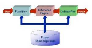
(courtesy of franck.dernoncourt)
- Fuzzication – this is where the input variables values (“crisp values”) are transformed into a grade ranging [0 .. 1]. In FL terminology, we define the “degree of membership” of this input variable to one “fuzzy set”.
- Rules Inference – this is where we define Rules (using Fuzzy Operators) which combine the Fuzzy variables computed before. There will be as many rules as needed to describe all the possible “behavior” of the system.
- Defuzzification – This is where all the Rules are combined to derive a decision (the output).
In “classical logic”, we are used to categorizing values in “sets”. For example, a LOW temperature will be all points below 5 degrees (celsius), WARM temperature will probably be above 50. We can already see the two main points differentiating the “classical logic” approach from the “fuzzy logic”.
- WARM, COLD are linguistic concepts which have no meaning per se and are context dependent. By saying that WARM is above 50 degrees, we implicitly define a context.
- The boundaries between those sets are clear (and abrupt).
Fuzzy logic deals precisely with the meaning of these “linguistic” concepts, by defining membership function for all the “subsets” (i.e. how much this measured temperature belongs to the WARM subset, to the COLD subset ?)
Moreover, hence the name, the boundaries between those subsets are … Fuzzy 🙂 and not clear. One temperature value can belong at the same time to the “WARM” subset and to the “COLD” subset. It is only the degree of membership that allows “rather cold” or “not too warm” notions to be expressed.
My Practical case
In our case we can define 3 fuzzy variables, each with appropriate subsets
Ambient Light intensity (subsets LOW, MID, HIGH), Motion quantity (subsets LOW, MODERATE, HIGH) and HR can be locked (subsets LOCKED, NOT LOCKED)
and the first set of rules, which defined our heuristic for finding out if the device is OFF ARM or not (OFF ARM means that it is NOT WORN 🙂
1. if motion low and hr not locked and ambient light high ==> certainly off-arm

2. if motion high and hr not locked and ambient light high ==> certainly off-arm

3. if motion low and hr not locked and (ambient light low or ambient light moderate) ==> certainly off-arm  (on a table)

4. if ambient light high ==> certainly off-arm (device alone facing up)

5. if motion high and hr not locked and ambient light moderate ==> probably off-arm

6. if motion high and hr not locked and ambient light low ==> probably off-arm (in hand moving)

7. if motion low and hr locked and light low ==> probably off-arm

8. if motion high and hr locked and light low ==> certainly not off-arm   (i.e. on arm)

9. if motion moderate and hr locked and ambient light low ==> certainly not off-arm (i.e. on arm)
This is quite a lot of Rules, and indeed it immediately calls for an optimisation in order to reduce their number. We’ll talk about that point at the Results/Improvement stage.
Membership functions
If we consider the Ambient Light intensity variable, we can define the three subsets boundaries as follow (crisp values are analog values out of the Light Sensor component)
- HIGH when the crisp value is above 200
- MID when the crisp value is between 50 and 100
- LOW when the crisp value is below 25
so the membership function will look like
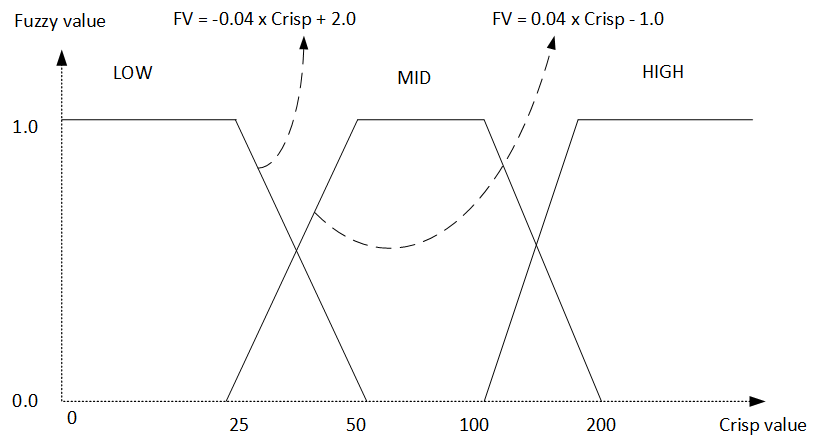
We can immediately deduce the 3 membership functions for this variable, using linear interpolation (as our sensor characteristic is linear).
static float LsMFunc_LOW (unsigned int_crisp)
{
    if (_crisp <= 25)
        return 1.0f;
    else if (_crisp >= 50)
        return 0.0f;
    else
        return((float)_crisp * (-0.04f)) + 2.0f;
}

static floatLsMFunc_MID (unsigned int_crisp)
{
    if(_crisp >= 50 && _crisp <= 100)
        return 1.0f;
    else if(_crisp <= 25 || _crisp >= 200)
        return0.0f;
    else
        if(_crisp <= 50)
            return((float)_crisp * (0.04f)) - 1.0f;
        else
            return ((float)_crisp * (-0.01f)) + 2.0f;
}

static floatLsMFunc_HIGH (unsigned int_crisp)
{
    if(_crisp <= 100)
        return0.0f;
    else if ((float)_crisp >= 200)
        return1.0f;
    else
        return((float)_crisp * (0.01f)) - 1.0f;
}
Non-linear sensors
The case is a bit more complicated for the Motion quantity (and similarly for the HR can be locked variable), as the value does not come from a linear sensor. We use both the” AnyMotion” and the “NoMotion” detection feature of our accelerometer. Both are combined by the controller into a composite “motion” variable as follows:
- When an AnyMotion is detected, the NoMotion value is decreased (and vice versa)
- When a NoMotion is detected once, it is no more detected (BMI spec). Therefore, the framework will generate fake “noMotion” events at the same rate, until AnyMotion is found.
The treatment of HR can be locked is similar, although the nature of this sensor is very different. It takes a lot of time to converge, and can also sometimes return no result.
For these reasons, we have used a running average process, so the value is smoothed and still we can absorb the parasitic events.
Next article will focus on the pure software implementation, and some results / paths for improvement.